Monday 12 September 2016

Driving motors using the Adafruit Motor Shield and the esp-12f


IMPORTANT.
The Adafruit Motor Shield normally gets its logic voltage from the Arduino Uno which runs at 5V,  and the ESP-12f uses 3.3V so you may think that a logic level converter is required and a 5V source. However the motor shield I2C and drive system works fine with connecting Vin to the 3.3V used by the esp-12f. The motors are power separately and you need to remove the Vin jumper.

The motor shield and esp-12f communicate using I2C.
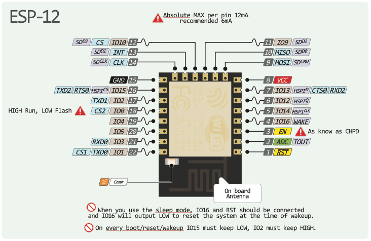
The pins on the ESP-12f are GPIO4( blue wire on my breadboard) is SDA and GPIO5 ( orange wire on my breadboard) is SCL.
The pins on the motor shield are as for  Arduino Uno as it i a shield, That is pin A4( analog 4) for SDA and pin A5(analog 5) for SCL. Note that similarity in numbers between the two devices.

The I2C address of the motor shield is hardcoded in the  library as 60.

Interfacing with the robot using a Web Browser

I next followed the tutorial in https://learn.adafruit.com/build-an-esp8266-mobile-robot. The simplest way is to clone the example code git repo into the Arduino sketches folder and
  1. eps8266_robot.ino - set the ssid and password appropriately, compile and upload
  2. scripts.js - set the ip address of the esp8266 
Then simply open the demo.html and you're off.

Thursday 8 September 2016

Reflashing the firmware of esp-12f

I basically followed the notes in Category:ESP8266_Firmware_and_SDK#Default_Firmware_.28ESP-12F.2C_and_the_series.29
I chose to use the Default firmware V1.3.0.2_AT_Firmware.bin.zip and the ESP_DOWNLOAD_TOOL_V2.4.exe with the parameters set as in the figure given in the first url.
Make sure you connect GPIO0 to ground and power on the esp-12f  before starting the download.
My first attempt failed with message "Open Port Failed"; which was because I had the port open from a Serial Monitor window.


Now make GPIO0 float and restart the esp-12f.

To test the new firmware I used Arduino IDE's Serial monitor and sent AT+GMR which gave the output below.


Now to try out some other firmwares!

D:\edwin\Downloads\V2.0_AT_Firmware(ESP)\v2.0 AT Firmware(ESP).bin
Fatal exception (0):
epc1=0x40201c04, epc2=0x00000000, epc3=0x00000000, excvaddr=0x00000000, depc=0x00000000
This leads to output on baud 74880:


 ets Jan  8 2013,rst cause:2, boot mode:(3,7)
load 0x40100000, len 816, room 16
tail 0
chksum 0x8d
load 0x3ffe8000, len 788, room 8
tail 12
chksum 0xcf
ho 0 tail 12 room 4
load 0x3ffe8314, len 288, room 12
tail 4
chksum 0xcf
csum 0xcf
2nd boot version : 1.2
  SPI Speed      : 40MHz
  SPI Mode       : QIO
  SPI Flash Size : 8Mbit
jump to run usererror user bin flag, flag = c
user code done
Done load empty sketch:

on baud 74880
Fatal exception (0): 
epc1=0x40202770, epc2=0x00000000, epc3=0x00000000, excvaddr=0x00000000, depc=0x00000000

Wednesday 7 September 2016

Using Arduino IDE for programming the ESP-12f

After the steps described in using-esp-12f-for-remote-control.html I decided to try to program the actual firmware using the Arduino IDE.  How to do this is described in many places e.g. esp8266-thing-hookup-guide/installing-the-esp8266-arduino-addon.


Use of GPI0

However I kept having failures when trying to upload the sketch. The reason was that to upload the firmware over serial I need to connect GPIO to ground rather than leaving it floating for actual running the saved firmware.


Picture of GPIO0, GPIO2 and GPIO15 pins

Running a webserver on esp-12f

esp8266-web-server-with-arduino-ide/

Resetting the ESP-12f firmware

Tuesday 6 September 2016

Using an ESP-12f for remote control

It may be possible to get rid of the Xbee and arduino approach and replace it with a single ESP-12f in the robot and a browser app to control it.

Parts list:
Perfect USB to TTL Converter CH340G STC 5V/3.3V 6Pin UART Serial Adapter Module from ebay for £0.99
Picture of B- USB to TTL UART Module CH340 3.3V/5V Serial Converter 

Note that I left the jumper across the OFF and 3.3v pins so that RX,TX are 3.3v compatible.

ESP8266 ESP-12F WiFi Wireless Wi-Fi Module + Vertical Breakout Board, UK, FAST for £5.85. Yes a bit expensive but I liked the breakout board.


3.3V power supply.


Connecting these together is given in many places.The figure below comes from http://www.instructables.com/id/Getting-Started-with-the-ESP8266-ESP-12/Picture of Make the connections

To send AT commands use the Serial Monitor in Arduino IDE with baudrate set to 115200

Adding wireless joystick control

The design is the 2 channels of  a 2-axis joystick such as the Parallax Inc 27800, 2-Axis Joystick HMI Module to 2 ADC channels of a Xbee radio. The Xbee is configured to monitor these two ADCs at a rate (IR) of every 200ms. The Xbee sends RX (Receive) Packet: 64-bit address I/O to all other Xbees on the same channel. This packet contains the values of the 2 ADC's.

Parallax Inc 27800, 2-Axis Joystick HMI Module

Another Xbee outputs the packet on it's own TX/RX lines. These are monitored by an Arduino. To demonstrate the communication I have written the sketch robot/sketches/Monitoring_Xbee_IO_packets/Monitoring_Xbee_IO_packets.ino in  https://github.com/epgibbons/robot.git  commit a3d9923efb7b3c30923d6eddbc6df9c8cec0c8f6.

The output displayed in the Serial Monitor window is of the form:
DIO4 is enabled = 1
ADC A0 is enabled  = 521
ADC A1 is enabled  = 511
DIO4 is enabled = 1
ADC A0 is enabled  = 521
ADC A1 is enabled  = 511
DIO4 is enabled = 1
ADC A0 is enabled  = 521
ADC A1 is enabled  = 511
DIO4 is enabled = 1
ADC A0 is enabled  = 521
 

Each axis has range 0-1023 with 521 when the joystick is in the default position.